總網頁瀏覽量

2012年12月17日 星期一

Arduino Interactive Shield (S4A Sensor Board)


介紹一塊新板子給初學者Arduino Interactive Shield (AIS)主要設計給ArduinoS4A初學者使用的一塊互動板,結合麥克風、按鍵開關、光源感測、滑桿式可變電阻、LED 、蜂鳴器等元件,以及四組RJ11的接頭可供外部連接其他裝置或元件,如溫濕度感測器、土壤濕度感測器等。另外預留一個藍芽孔位給需要無線傳輸的使用者。可利用此無線傳輸跟Android手機或電腦溝通。AIS板子上也預留六根數位腳位給其他需要外部電源的裝置使用,例如連接多個伺服馬達。

一.     內容說明及特點:


特點:
1. 四個RJ11接頭容易外接其他裝置(D2/D3, A3,A4,A5)
2. 一個一公分大小的按鍵開關(D2)
3. 一個蜂鳴器(D9)
4. 一個麥克風( A2)
5. 兩顆 LED 顯示,一顆為紅色(D10),一顆為綠色(D11)
6. 一個滑桿可變電阻(10K),有效行程65mm.(A0)
7. 一個光感測元件(A1)
8. 預留一個藍芽孔位(UART)
9. RJ11接頭可用電話線連接至少10米距離的感測元件


Motoduino資訊: http://motoduino.com


2012年9月20日 星期四

Arduino USB Keyboard = Arduino UNO + USB Host shield + USB keyboard

這次把做好許久的Arduino USB keyboard的做法及程式公開, 讓想學如何用USB host連接 keyboard的網友做參考(有不少網友寫mail來希望可以post出來).

DIY的材料:
1. Arduino UNO or compatible
2. USB host shield
3. USB keyboard

參考連接圖:


程式如下:  完整程式 (sketch)
------------------------------------------------------

#include <avr/pgmspace.h>

#include <avrpins.h>
#include <max3421e.h>
#include <usbhost.h>
#include <usb_ch9.h>
#include <Usb.h>
#include <usbhub.h>
#include <avr/pgmspace.h>
#include <address.h>
#include <hidboot.h>

#include <printhex.h>
#include <message.h>
#include <hexdump.h>
#include <parsetools.h>

class KbdRptParser : public KeyboardReportParser
{
        void PrintKey(uint8_t mod, uint8_t key);
        
protected:
virtual void OnKeyDown (uint8_t mod, uint8_t key);
virtual void OnKeyUp (uint8_t mod, uint8_t key);
virtual void OnKeyPressed(uint8_t key);
};

USB     Usb;
HIDBoot<HID_PROTOCOL_KEYBOARD>    Keyboard(&Usb);
uint32_t next_time;
KbdRptParser Prs;

void KbdRptParser::PrintKey(uint8_t m, uint8_t key)
{
    MODIFIERKEYS mod;
    *((uint8_t*)&mod) = m;
    Serial.print((mod.bmLeftCtrl   == 1) ? "C" : " ");
    Serial.print((mod.bmLeftShift  == 1) ? "S" : " ");
    Serial.print((mod.bmLeftAlt    == 1) ? "A" : " ");
    Serial.print((mod.bmLeftGUI    == 1) ? "G" : " ");
    
    Serial.print(" >");
    PrintHex<uint8_t>(key);
    Serial.print("< ");

    Serial.print((mod.bmRightCtrl   == 1) ? "C" : " ");
    Serial.print((mod.bmRightShift  == 1) ? "S" : " ");
    Serial.print((mod.bmRightAlt    == 1) ? "A" : " ");
    Serial.println((mod.bmRightGUI    == 1) ? "G" : " ");
};

void KbdRptParser::OnKeyDown(uint8_t mod, uint8_t key)
{
    Serial.print("DN ");
    PrintKey(mod, key);
    uint8_t c = OemToAscii(mod, key);
    
    if (c)
        OnKeyPressed(c);
}

void KbdRptParser::OnKeyUp(uint8_t mod, uint8_t key)
{
    Serial.print("UP ");
    PrintKey(mod, key);
}

void KbdRptParser::OnKeyPressed(uint8_t key)
{
  int moveSteps;
    Serial.print("ASCII: ");
    Serial.println((char)key);
}

void setup()
{
    Serial.begin(115200);
    Serial.println("Start.......");

    if (Usb.Init() == -1)
        Serial.println("Usb initial falied");
      
    delay( 200 );
  
    next_time = millis() + 5000;
  
    Keyboard.SetReportParser(0, (HIDReportParser*)&Prs);

}

void loop()
{
    Usb.Task();
}


---------------------------------------------

Video(control stepper motors) : http://www.youtube.com/watch?v=z4d_EpXNxgo


2012年8月23日 星期四

Arduino PIR eMail Alarm = Arduino + PIR Sensor + WiFi Shield + Google Engine App


The PIR alert can be located at home. Arduino will send messages to Google engine app when PIR detects someone moving. I designed a simple app(email sending) on google app engine (everdevice.appspot.com) to receive messages from arduino, and then send a email to someone you want. If you don't mind the default email sender(my email address), you may try it by my sketch in my blog. In this practice, I replaced Arduino with Motoduino, and on 3G wireless environment(3G share point). Note: if you used AP router, please check the AP router setting whether it is not available by IP address direct hookup.

利用人體紅外線感測器偵測到物體移動時會發出Email通知, 此裝置放在住家或防止小偷侵入的場所是非常適合,如果不介意內設的Email發出者,有興趣的Arduino 網友可以試試底下程式!
主要利用我寫的一個google engine app (everdevice.appspot.com)專門接收arduino送來的message,然後再轉成email送出.

DIY Material:
1. Arduino or Motoduino
2. Arduino WiFi Shield
3.PIR Sensor
4. WiFi AP Router

Arduino Sketch:    
--------------------- Begin of Sketch ----------------


#include <WiServer.h>
// Wireless configuration parameters -
unsigned char local_ip[]= {192,168,1,165};   // IP address of WiShield (modify it)
unsigned char gateway_ip[]= {192,168,1,1};   // router or gateway IP address (modify it)
unsigned char subnet_mask[]= {255,255,255,0}; // subnet mask for the local network
char ssid[] = {"Arduino"};   // max 32 bytes  (modify it)
unsigned char security_type = 0;               // 0 - open; 1 - WEP; 2 - WPA; 3 - WPA2   (modify it)
// WPA/WPA2 passphrase
const prog_char security_passphrase[] PROGMEM = {"0123456789"}; // max 64 characters

// WEP 128-bit keys
prog_uchar wep_keys[] PROGMEM = {
0x00, 0x00, 0x00, 0x00, 0x00, 0x00, 0x00, 0x00, 0x00, 0x00, 0x00, 0x00, 0x00, // Key 0
0x00, 0x00, 0x00, 0x00, 0x00, 0x00, 0x00, 0x00, 0x00, 0x00, 0x00, 0x00, 0x00, // Key 1
0x00, 0x00, 0x00, 0x00, 0x00, 0x00, 0x00, 0x00, 0x00, 0x00, 0x00, 0x00, 0x00, // Key 2
0x00, 0x00, 0x00, 0x00, 0x00, 0x00, 0x00, 0x00, 0x00, 0x00, 0x00, 0x00, 0x00 // Key 3
};

// setup the wireless mode; infrastructure - connect to AP; adhoc - connect to another WiFi device
#define WIRELESS_MODE_INFRA 1
#define WIRELESS_MODE_ADHOC 2
unsigned char wireless_mode = WIRELESS_MODE_INFRA;
unsigned char ssid_len;
unsigned char security_passphrase_len;
// End of wireless configuration parameters ----------------------------------------

uint8 ip[] = {74,125,31,141}; //IP address of everdevice.appspot.com
char hostName[] = "everdevice.appspot.com"; // google engine app
char  url[]="/mygaetest?action=sendmail&to=xxxx@xxxx.xxx&device=DHT11&value=33&body=this";
         // From user: sinocgtchen@gmail.com (default)
         // To user: xxxx@xxxx.xxx (modify it)
         // device : device name (modify it)
         // body : mail body (modify it)

GETrequest getEverDevice(ip, 80, hostName, url);
int pirPin = 3;    //the digital pin connected to the PIR sensor's output
int ledPin = 13;
/////////////////////////////
//VARS
//the time we give the sensor to calibrate (10-60 secs according to the datasheet)
int calibrationTime = 30;      
//the time when the sensor outputs a low impulse
long unsigned int lowIn;      

//the amount of milliseconds the sensor has to be low
//before we assume all motion has stopped
long unsigned int pause = 5000;

boolean lockLow = true;
boolean takeLowTime;
boolean detected = false;
void setup()
{
   Serial.begin(57600);
   pinMode(pirPin, INPUT);
  digitalWrite(pirPin, LOW);
  Serial.print("calibrating sensor ");
    for(int i = 0; i < calibrationTime; i++){
      Serial.print(".");
      delay(1000);
      }
    Serial.println(" done");
    Serial.println("SENSOR ACTIVE");

    Serial.println("WiFi init...");
   WiServer.init(NULL);
    getEverDevice.setReturnFunc(printData);
    delay(50);
}

void loop()
{
  if(PIR_detected() && (detected))
  {  // PIR : HIGH
      getEverDevice.submit();  
      Serial.println("email sending");
   }
   // Run WiServer
   WiServer.server_task();
    delay(1000);
}

void printData(char* data, int len) {
  while (len-- > 0) {
    Serial.print(*(data++));
  }
}

boolean PIR_detected()
{
  boolean bPIR;

     if(digitalRead(pirPin) == HIGH){
       digitalWrite(ledPin, HIGH);   //the led visualizes the sensors output pin state
       detected = false;
       if(lockLow){
         //makes sure we wait for a transition to LOW before any further output is made:
         lockLow = false;          
         Serial.println("---");
         Serial.print("motion detected at ");
         Serial.print(millis()/1000);
         Serial.println(" sec");
     
         detected = true;
         delay(50);
         }      
         takeLowTime = true;
       
         bPIR = true;

       }
   
     if(digitalRead(pirPin) == LOW){    
       digitalWrite(ledPin, LOW);  //the led visualizes the sensors output pin state
     
       if(takeLowTime){
        lowIn = millis();          //save the time of the transition from high to LOW
        takeLowTime = false;       //make sure this is only done at the start of a LOW phase
        }
       //if the sensor is low for more than the given pause,
       //we assume that no more motion is going to happen
       if(!lockLow && millis() - lowIn > pause){
           //makes sure this block of code is only executed again after
           //a new motion sequence has been detected
           lockLow = true;                      
           Serial.print("motion ended at ");      //output
           Serial.print((millis() - pause)/1000);
           Serial.println(" sec");
           delay(50);
           }
           bPIR = false;
       }
    return bPIR;
}


------------------------------ End of Sketch --------------------------

Video here: http://youtu.be/kLGKAwNrjKk

More Video: http://www.youtube.com/user/sinocgtchen

My Blog(DIY) : http://sinocgtchen.blogspot.com

Motoduino information: http://motoduino.com
My email : sinocgtchen@gmail.com

2012年8月4日 星期六

Arduino PS2 Keyboard Controls DC Motor

PS2 keyboard connected to Arduino to control a DC motor. The motor speed will be increased 10 units when pressed UPARROW key once, decreased 10 units when pressed DOWNARROW key once.

DIY Material:
1. Motoduino (Arduino + L293D)
2. PS2 Keyboard
3. 5V DC Motor
4. 9V battery
5. Female PS2 Connector

Description:
    Pin connection:
    PS2         Ardunio
      1     -->     3
      2     -->     No Connection
     3      -->     GND
     4      -->     Vcc
     5      -->    2
     6      -->    No Connection  


Arduino  Sketch:

#include <PS2Keyboard.h>

const int DataPin = 3;  // PS2 data pin
const int IRQpin =  2;  // PS2 clock pin

PS2Keyboard keyboard;
const int Motor_E1 = 5; // digital pin 5 of Arduino (PWM)    
const int Motor_E2 = 6;  // digital pin 6 of Arduino (PWM)  
const int Motor_M1 = 7;     // digital pin 7 of Arduino
const int Motor_M2 = 8;    // digital pin 8 of Arduino

int motorSpeed = 0;

void setup() {
  delay(1000);
  keyboard.begin(DataPin, IRQpin);
  Serial.begin(57600);
  Serial.println("Keyboard Ready:");
  
  pinMode(Motor_M1, OUTPUT);

}

void loop() {
  
  if (keyboard.available()) {
    
    // read the next key
    char c = keyboard.read();
    
    switch(c)
    {
      case PS2_LEFTARROW:
      case PS2_RIGHTARROW:
      case PS2_UPARROW:
                motorSpeed = motorSpeed + 10;
                if(motorSpeed > 255)
                    motorSpeed = 255;
                break;
      case PS2_DOWNARROW:
                motorSpeed = motorSpeed - 10;
                if(motorSpeed <= 0 )
                    motorSpeed = 0;
                break;
      case PS2_ENTER:
      case PS2_TAB:
      case PS2_ESC:
      case PS2_PAGEDOWN:
      case PS2_PAGEUP:
      case PS2_DELETE:
                  break;
    }
    
    motor(0, motorSpeed);
  }
}

void motor(byte flag, int motorspeed)
{
  digitalWrite( Motor_M1, HIGH);
  analogWrite( Motor_E1, motorspeed);
  
  Serial.println("motor speed: ");
  Serial.println(motorspeed);
}

-------------------------------------------------


Motoduino Information: http://motoduino.com
My Email : sinocgtchen@gmail.com

2012年7月18日 星期三

Clock = Arduino / Motoduino + RTC (DS1307) + SPI LED (7-Segment)

利用RTC module和LED七段顯示器做出一個簡單的時鐘, SPI介面可以省去許多arduino的IO pin.


DIY材料:
1.Arduino
2.RTC (DS1307) module
3.SPI LED module(7-segment)
4.Inteface Shield (option)
5.9V battery

Arduino sketch:

#include <stdio.h>
#include <string.h>
#include <DS1302.h>

//Pin connected to latch pin (ST_CP) of 74HC595
const int latchPin = 8;
//Pin connected to clock pin (SH_CP) of 74HC595
const int clockPin = 3;
////Pin connected to Data in (DS) of 74HC595
const int dataPin = 9;
byte Tab[]={0xc0,0xf9,0xa4,0xb0,0x99,0x92,0x82,0xf8,0x80,0x90,0xff};
byte Dot = 0x7f;
boolean DotOn;
/* Set the appropriate digital I/O pin connections */
uint8_t CE_PIN   = 5;  //RST
uint8_t IO_PIN   = 6;
uint8_t SCLK_PIN = 7;

/* Create buffers */
char buf[50];
char day[10];

/* Create a DS1302 object */
DS1302 rtc(CE_PIN, IO_PIN, SCLK_PIN);

void clearAll()
{
  for(int i=0; i<8; i++)
  {
    digitalWrite(latchPin, LOW);
    shiftOut(dataPin, clockPin, MSBFIRST, 0xff);
    digitalWrite(latchPin, HIGH);
    delay(10);
  }
}

void displayTime(byte h1, byte h2, byte m1, byte m2, byte s1, byte s2)
{
  if (DotOn)
  {
  digitalWrite(latchPin, LOW);
  // shift the bits out:
  shiftOut(dataPin, clockPin, MSBFIRST, s2);
  shiftOut(dataPin, clockPin, MSBFIRST, s1);
  shiftOut(dataPin, clockPin, MSBFIRST, Dot);
  shiftOut(dataPin, clockPin, MSBFIRST, m2);
  shiftOut(dataPin, clockPin, MSBFIRST, m1);
  shiftOut(dataPin, clockPin, MSBFIRST, Dot);
  shiftOut(dataPin, clockPin, MSBFIRST, h2);
  shiftOut(dataPin, clockPin, MSBFIRST, h1);
    // turn on the output so the LEDs can light up:
  digitalWrite(latchPin, HIGH);
  DotOn = false;
  }
  else
  {
  digitalWrite(latchPin, LOW);
  // shift the bits out:
  shiftOut(dataPin, clockPin, MSBFIRST, s2);
  shiftOut(dataPin, clockPin, MSBFIRST, s1);
  shiftOut(dataPin, clockPin, MSBFIRST, 0xff);
  shiftOut(dataPin, clockPin, MSBFIRST, m2);
  shiftOut(dataPin, clockPin, MSBFIRST, m1);
  shiftOut(dataPin, clockPin, MSBFIRST, 0xff);
  shiftOut(dataPin, clockPin, MSBFIRST, h2);
  shiftOut(dataPin, clockPin, MSBFIRST, h1);
    // turn on the output so the LEDs can light up:
  digitalWrite(latchPin, HIGH);
   DotOn = true;
  }
}

void print_time()
{
  /* Get the current time and date from the chip */
  Time t = rtc.time();

  /* Name the day of the week */
  memset(day, 0, sizeof(day));  /* clear day buffer */
  int Hour1 = t.hr/10;
  int Hour2 = t.hr%10;
  int min1 = t.min/10;
  int min2 = t.min%10;
  int sec1 = t.sec/10;
  int sec2 = t.sec%10;
 
  byte   h1 = Tab[Hour1];
  byte   h2 = Tab[Hour2];
  byte   m1 = Tab[min1];
  byte   m2 = Tab[min2];
  byte   s1 = Tab[sec1];
  byte   s2 = Tab[sec2];

    displayTime(h1, h2, m1, m2, s1, s2);
}


void setup()
{
  Serial.begin(57600);
  //set pins to output because they are addressed in the main loop
  pinMode(latchPin, OUTPUT);
  pinMode(dataPin, OUTPUT);
  pinMode(clockPin, OUTPUT);

  rtc.write_protect(false);
  rtc.halt(false);

  /* Make a new time object to set the date and time */
  Time t(2012, 7, 11, 21, 16, 37, 3);

  /* Set the time and date on the chip */
  rtc.time(t);
    clearAll();
}


/* Loop and print the time every second */
void loop()
{
  print_time();
  delay(1000);
}


Video: http://www.youtube.com/watch?v=RAb9WjOctdU

My Blog:  http://sinocgtchen.blogspot.com
More videos: http://www.youtube.com/user/sinocgtchen
Motoduino information: http://motoduino.com
My Email: sinocgtchen@gmail.com

2012年7月13日 星期五

自動循線車(Line Following Car) = Motoduino (Arduino + L293D) + IR Sensors


之前忘記POST這篇DIY的過程給大家分享,現在利用一點時間說明一下, 這次使用 Motoduino 來做循線車是很容易的一件事, 只要加一個 Tracker Sensor(IR Sensor) 及修改Arduino程式即完成. 

DIY材料:
1.Motoduino 或 (Arduino Duemilanove + Motor shield)
2.Tracker Sensor (IR Sensor)
3.小車本體
4. 9V battery


Sketch(Arduino程式):

// Sensor sequence: SLeftLeft SMiddle SRightRight
const int SLeftLeft = 9;      //左感測器輸入腳
const int SMiddle = 10;     //中間感測器輸入腳
const int SRightRight = 11;     //右感測器輸入腳

// variables will change:
int SLL;    //左感測器狀態
int SM;    //中感測器狀態
int SRR;    //右感測器狀態
const int Motor_M1 = 7;  
const int Motor_M2 = 8;  
const int Motor_E1 = 5;    
const int Motor_E2 = 6;  

byte byteSensorStatus=0;

#define SENSOR_L 4;
#define SENSOR_M 2;
#define SENSOR_R 1;

void setup() {
   //set up serial communications
   Serial.begin(9600);

  // 輸出入接腳初始設定
  pinMode(SLeftLeft, INPUT);
  pinMode(SMiddle, INPUT);
  pinMode(SRightRight, INPUT);
  pinMode(Motor_M1, OUTPUT);
  pinMode(Motor_M2, OUTPUT);
}

void loop(){
  byteSensorStatus = 0;
  // 讀取感測器狀態值
  SLL = digitalRead(SLeftLeft);
  if(SLL == 1)
     byteSensorStatus = (byteSensorStatus | (0x01 << 2));
  SM = digitalRead(SMiddle);
  if(SM == 1)
     byteSensorStatus = (byteSensorStatus | (0x01 << 1));
  SRR = digitalRead(SRightRight);
  if(SRR == 1)
     byteSensorStatus = (byteSensorStatus | 0x01);
//   Serial.println(byteSensorStatus, HEX);
  switch(byteSensorStatus)
  { // 0:
    case 0: // SL:0 SM:0 SR:0
            motorstop(0,0);
            break;
    case 1: // SL:0 SM:0 SR:1
            left(0,0);
            break;
    case 2: // SL:0 SM:1 SR:0
            motorstop(0,0);
            break;
    case 3: // SL:0 SM:1 SR:1
            left(0,0);
            break;
    case 4: // SL:1 SM:0 SR:0
             right(0,0);
             break;
    case 5: // SL:1 SM:0 SR:1
             forward(0,0);
             break;
    case 6: // SL:1 SM:1 SR:0
             right(0,0);
             break;
    case 7: // SL:1 SM:1 SR:1
             forward(0,0);
  }
}

void motorstop(byte flag, byte numOfValues)
{
  digitalWrite( Motor_E1, 0);
  digitalWrite( Motor_E2, 0);
  Serial.println("stop : ");
}

void forward(byte flag, byte numOfValues)
{
  digitalWrite( Motor_M1, HIGH);
  digitalWrite( Motor_M2, HIGH);
  analogWrite( Motor_E1, 255);
  analogWrite( Motor_E2, 255);
}

void back(byte flag, byte numOfValues)
{
  digitalWrite( Motor_M1, LOW);
  digitalWrite( Motor_M2, LOW);
  analogWrite( Motor_E1, 255);
  analogWrite( Motor_E2, 255);
}

void right(byte flag, byte numOfValues)
{
  digitalWrite( Motor_M1, HIGH);
  digitalWrite( Motor_M2, HIGH);
  analogWrite( Motor_E1, 255);
  analogWrite( Motor_E2, 0);
}

void left(byte flag, byte numOfValues)
{
  digitalWrite( Motor_M1, HIGH);
  digitalWrite( Motor_M2, HIGH);
  analogWrite( Motor_E1, 0);
  analogWrite( Motor_E2, 255);
}

--------------------------------------------------------------------------

The video demonstration: http://www.youtube.com/watch?v=NkF-v1hor-U&list=UU6aKpj71jLKYABYLr3Wbpuw&index=2&feature=plcp

Motoduino information: http://motoduino.com
My Email: sinocgtchen@gmail.com

2012年6月23日 星期六

Arduino / motoduino controls 7 Servos + 1 Stepper Motor (步進馬達)

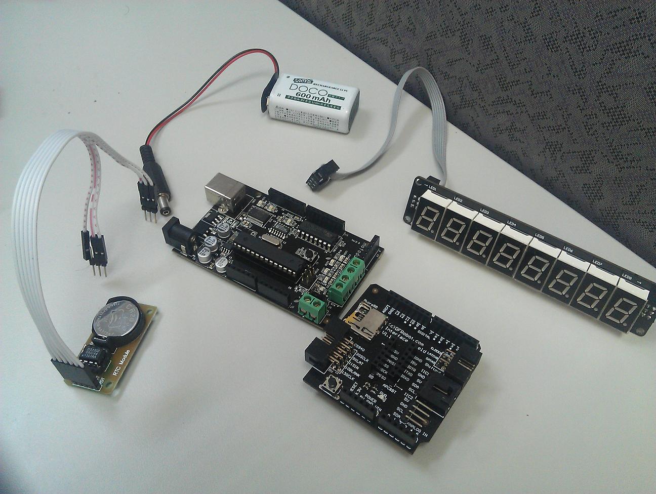
做了一個簡單實驗, 利用Arduino/Motoduino控制七顆伺服馬達(手上只有七顆)和一顆步進馬達(2-Phase)運轉,運轉還算順暢! 主要利用 I/O Expansion Shield疊在motoduino上,除了馬達電線容易接線外,還可讓七顆伺服馬達吃外部電源.DIY material (材料):
1. Motoduino (Arduino + L293D motor driver)
2. I/O Expansion shield
3. Servo motor (伺服馬達) x 7 
4. Stepper Motor(步進馬達 二相四線)  x 1
5. 9V Battery x 2


接線圖

接線圖

                                                              I/O Expansion Shield V5


Arduino Sketch: (有興趣網友可以把重複程式建立function來呼叫)


#include <Stepper.h>
#include <Servo.h>

Servo servo12;          // Define servo12
Servo servo11;          // Define servo11
Servo servo10;          // Define servo10
Servo servo9;          // Define servo9
Servo servo4;          // Define servo4
Servo servo3;          // Define servo3
Servo servo2;          // Define servo2

const int stepsPerRevolution = 200;  // change this to fit the number of steps per revolution                                 // for your motor
const int Motor_E1 = 5; // digital pin 5 of Arduino (PWM)  
const int Motor_E2 = 6;  // digital pin 6 of Arduino (PWM)
const int Motor_M1 = 7;     // digital pin 7 of Arduino
const int Motor_M2 = 8;    // digital pin 8 of Arduino
   
Stepper myStepper(stepsPerRevolution, Motor_M1, Motor_M2);          
int pos = 0;

void setup() {
  // set the speed at 60 rpm:
  myStepper.setSpeed(60);
  // initialize the serial port:
  Serial.begin(9600);
  pinMode(Motor_M1, OUTPUT);
  pinMode(Motor_M2, OUTPUT);

  digitalWrite( Motor_E1, HIGH);  // speed control
  digitalWrite( Motor_E2, HIGH);  // speed control

  servo12.attach(12);
  servo11.attach(11);
  servo10.attach(10);
  servo9.attach(9);
  servo4.attach(4);
  servo3.attach(3);
  servo2.attach(2);

}

void loop() {
  // step one revolution  in one direction:
//   Serial.println("clockwise");
  myStepper.step(200);
  delay(500);

for(pos = 0; pos < 180; pos += 1)  // goes from 0 degrees to 180 degrees
  {                                  // in steps of 1 degree
    servo12.write(pos);              // tell servo to go to position in variable 'pos'
    servo11.write(pos);              // tell servo to go to position in variable 'pos'
    servo10.write(pos);              // tell servo to go to position in variable 'pos'
    servo9.write(pos);              // tell servo to go to position in variable 'pos'
    servo4.write(pos);              // tell servo to go to position in variable 'pos'
    servo3.write(pos);              // tell servo to go to position in variable 'pos'
    servo2.write(pos);              // tell servo to go to position in variable 'pos'
    delay(10);                       // waits 15ms for the servo to reach the position
  }
  for(pos = 180; pos>=1; pos-=1)     // goes from 180 degrees to 0 degrees
  {                              
    servo12.write(pos);              // tell servo to go to position in variable 'pos'
    servo11.write(pos);              // tell servo to go to position in variable 'pos'
    servo10.write(pos);              // tell servo to go to position in variable 'pos'
    servo9.write(pos);              // tell servo to go to position in variable 'pos'
    servo4.write(pos);              // tell servo to go to position in variable 'pos'
    servo3.write(pos);              // tell servo to go to position in variable 'pos'
    servo2.write(pos);              // tell servo to go to position in variable 'pos'
    delay(10);                       // waits 15ms for the servo to reach the position
  }
for(pos = 0; pos < 180; pos += 1)  // goes from 0 degrees to 180 degrees
  {                                  // in steps of 1 degree
    servo12.write(pos);              // tell servo to go to position in variable 'pos'
    servo11.write(pos);              // tell servo to go to position in variable 'pos'
    servo10.write(pos);              // tell servo to go to position in variable 'pos'
    servo9.write(pos);              // tell servo to go to position in variable 'pos'
    servo4.write(pos);              // tell servo to go to position in variable 'pos'
    servo3.write(pos);              // tell servo to go to position in variable 'pos'
    servo2.write(pos);              // tell servo to go to position in variable 'pos'
    delay(10);                       // waits 15ms for the servo to reach the position
  }
  for(pos = 180; pos>=1; pos-=1)     // goes from 180 degrees to 0 degrees
  {                              
    servo12.write(pos);              // tell servo to go to position in variable 'pos'
    servo11.write(pos);              // tell servo to go to position in variable 'pos'
    servo10.write(pos);              // tell servo to go to position in variable 'pos'
    servo9.write(pos);              // tell servo to go to position in variable 'pos'
    servo4.write(pos);              // tell servo to go to position in variable 'pos'
    servo3.write(pos);              // tell servo to go to position in variable 'pos'
    servo2.write(pos);              // tell servo to go to position in variable 'pos'
    delay(10);                       // waits 10ms for the servo to reach the position
  } `
  for(pos = 0; pos < 180; pos += 1){  // goes from 0 degrees to 180 degrees
    servo12.write(pos);    // tell servo to go to position in variable 'pos'
    delay(10);
  }
  for(pos = 0; pos < 180; pos += 1){  // goes from 0 degrees to 180 degrees
    servo11.write(pos);              // tell servo to go to position in variable 'pos'
    delay(10);
  }
  for(pos = 0; pos < 180; pos += 1){  // goes from 0 degrees to 180 degrees
    servo10.write(pos);              // tell servo to go to position in variable 'pos'
    delay(10);
  }
  for(pos = 0; pos < 180; pos += 1){  // goes from 0 degrees to 180 degrees
    servo9.write(pos);              // tell servo to go to position in variable 'pos'
    delay(10);
  }
  for(pos = 0; pos < 180; pos += 1) { // goes from 0 degrees to 180 degrees
    servo4.write(pos);              // tell servo to go to position in variable 'pos'
    delay(10);
  }
  for(pos = 0; pos < 180; pos += 1) { // goes from 0 degrees to 180 degrees
    servo3.write(pos);              // tell servo to go to position in variable 'pos'
    delay(10);
  }
  for(pos = 0; pos < 180; pos += 1) { // goes from 0 degrees to 180 degrees
    servo2.write(pos);              // tell servo to go to position in variable 'pos'
    delay(10);
  }

  for(pos = 180; pos>=1; pos-=1) {    // goes from 180 degrees to 0 degrees
    servo2.write(pos);              // tell servo to go to position in variable 'pos'
    delay(10);
  }
  for(pos = 180; pos>=1; pos-=1) {    // goes from 180 degrees to 0 degrees
    servo3.write(pos);              // tell servo to go to position in variable 'pos'
    delay(10);
  }
  for(pos = 180; pos>=1; pos-=1) {    // goes from 180 degrees to 0 degrees
    servo4.write(pos);              // tell servo to go to position in variable 'pos'
    delay(10);
  }
  for(pos = 180; pos>=1; pos-=1) {    // goes from 180 degrees to 0 degrees
    servo9.write(pos);              // tell servo to go to position in variable 'pos'
    delay(10);
  }
  for(pos = 180; pos>=1; pos-=1) {    // goes from 180 degrees to 0 degrees
    servo10.write(pos);              // tell servo to go to position in variable 'pos'
    delay(10);
  }
  for(pos = 180; pos>=1; pos-=1) {    // goes from 180 degrees to 0 degrees
    servo11.write(pos);              // tell servo to go to position in variable 'pos'
    delay(10);
  }
  for(pos = 180; pos>=1; pos-=1) {    // goes from 180 degrees to 0 degrees
    servo12.write(pos);              // tell servo to go to position in variable 'pos'
    delay(10);
  }

  for(pos = 0; pos < 180; pos+=1) {    // goes from 0 degrees to 180 degrees
    servo12.write(pos);              // tell servo to go to position in variable 'pos'
    servo11.write(pos);              // tell servo to go to position in variable 'pos'
    delay(5);
  }

  for(pos = 180; pos >=1; pos-=1) {    // goes from 180 degrees to 0 degrees
    servo12.write(pos);
    servo11.write(pos);              // tell servo to go to position in variable 'pos'
    delay(5);
  }
   myStepper.step(-200);
  delay(500);
}


Video:  http://www.youtube.com/watch?v=rB-noWhgbXM&list=UU6aKpj71jLKYABYLr3Wbpuw&index=1&feature=plcp


更多影片請看: http://www.youtube.com/user/sinocgtchen
部落格 : http://sinocgtchen.blogspot.com
Motoduino資訊: http://motoduino.com


2012年4月24日 星期二

Color Shield Remote Control = Motoduino / Arduino + Bluetooth + Android + RGB LED 8x8

Arduino Color Shield 加上 RGB LED 很適合做學生專題及LED基本學習, Color shield 是Colorduino的簡易版,主要差在color shield無法繼續串接下去,只有8x8 RGB LED可顯示,顯示的顏色有 256x256x256這麼多種顏色. 此範例配合Android手機藍芽控制RGB LED亮或暗.

DIY材料:
1. Motoduino / Arduino
2. Bluetooth
3. Arduino Color Shield
4. 8x8 RGB LED
5. Android 手機

                                                                 Motoduino

                                                                  Arduino Colors Shield


                                                                   8x8 RGB LED

                                                                 組合上去

                                                             8x8 RGB LED

影片請看: http://www.youtube.com/watch?v=UBoWGyyYmic

更多影片請看: http://www.youtube.com/user/sinocgtchen
部落格 : http://sinocgtchen.blogspot.com
Motoduino資訊: http://motoduino.com


2012年4月20日 星期五

Changes Bluetooth Baud Rate / Name on Motoduino/Arduino (AT Command)

這次來說明另一個簡單的方式修改bluetooth設定值,利用Arduino IDE直接下AT Command給bluetooth修改藍芽名稱或Baud Rate等, 此範例以藍芽名稱為例, 修改Baud Rate方法一樣,AT Command不一樣而已.

步驟如下:
1.把Motoduino/Arduino MCU 移除,如下圖:


2. 需要一條4 pin 或 6 pin排線把BT跟Motoduino做連接,注意Bluetooth的RX接Motoduino/Arduino的RX, Bluetooth的TX接Motoduino/Arduino的TX. Bluetooth的Vcc接 板子Vcc, GND接GND, 只需接四根pin腳.如下圖:


3. 把板子連接PC, 打開Arduino IDE 選擇正確的 Serial Port,如下圖:


4. 注意Arduino IDE的baud rate設定,如果Bluetooth目前default baud rate是 57600,則設定為57600,和No Line Ending. 如下圖:


5. 開始下AT Command給bluetooth, 下 AT 則會回應 OK, 在此以修改藍芽名稱為例, AT+NAMEMOTOBT , ( 如修改baud rate則 AT+BAUD7 表示設定baud rate成 57600)


 6. Bluetooth 回應的訊息, OKsetname表示藍芽名稱修改完成.
                                                   
7. 移除板子電源,把Atmega328P or MCU 插上板子還原. 這樣就大功告成!!


部落格 : http://sinocgtchen.blogspot.com
Motoduino資訊: http://motoduino.com


2012年4月18日 星期三

手機遙控智慧車 = Motoduino(Arduino + L293D) + two Servos (伺服馬達) + Bluetooth

把兩顆伺服馬達(兩個自由度,可以承受13kg大扭力)架設在小車子上,且把照相功能的攝影鏡頭架在伺服馬達上,利用Motoduino跟藍芽傳輸控制訊號,Android­手機可以控制鏡頭角度,目前照相功能未整合進去,不過測試是沒問題的,下一階段在整合進去...


DIY使用材料:
1. Motoduino (Arduino + L293D)
2. Bluetooth module
3. MG995 Servo  x 2
4. 9V battery
5. 兩輪小車一台
6. IO Expansion Shield (option, 可省略)
7. Android phone


                                        IO Expansion Shield
  
                                                          
                                         MG995 伺服馬達


    影片:  http://www.youtube.com/watch?v=Ass0XSu98wE


更多影片請看: http://www.youtube.com/user/sinocgtchen
部落格 : http://sinocgtchen.blogspot.com
Motoduino資訊: http://motoduino.com


2012年4月8日 星期日

Stepper Motor Control (步進馬達控制) = Motoduino (Arduino+293D) + Stepper Motor

Motoduino這塊板子也可以控制步進馬達(stepper motor), 方法很簡單, 手上這顆是二相激磁四線式步進馬達, 電壓 5V, 精度1.8度, 電流 0.3A, 四線接法: 紅線接M1+, 棕色接M1-, 藍色接 M2-, 黃色接 M2+. 影片中實驗是順時針走 200步(200x1.8度=360)剛好一圈,逆時針走200步回原點. 


 影片請參考這裡 : http://www.youtube.com/watch?v=AIZBQgjQ3rQ

使用材料:


1. Motoduino
2. Stepper Motor (KH42JM2B011) 5V, 0.3A, 1.8 Deg.


The Sketch(for Motoduino):


#include <Stepper.h>

const int stepsPerRevolution = 200;  // change this to fit the number of steps per revolution
                                     // for your motor
const int Motor_E1 = 5; // digital pin 5 of Arduino (PWM)  
const int Motor_E2 = 6;  // digital pin 6 of Arduino (PWM)
const int Motor_M1 = 7;     // digital pin 7 of Arduino
const int Motor_M2 = 8;    // digital pin 8 of Arduino
//Stepper myStepper(stepsPerRevolution, 8,9,10,11);          
Stepper myStepper(stepsPerRevolution, Motor_M1, Motor_M2);          

void setup() {
  // set the speed at 60 rpm:
  myStepper.setSpeed(60);
  // initialize the serial port:
  Serial.begin(9600);
  pinMode(Motor_M1, OUTPUT);
  pinMode(Motor_M2, OUTPUT);

  digitalWrite( Motor_E1, HIGH);  // speed control
  digitalWrite( Motor_E2, HIGH);  // speed control
}

void loop() {
  // step one revolution  in one direction:
   Serial.println("clockwise");
  myStepper.step(stepsPerRevolution);
  delay(500);

   // step one revolution in the other direction:
  Serial.println("counterclockwise");
  myStepper.step(-stepsPerRevolution);
  delay(500);
}


Blog: http://sinocgtchen.blogspot.com
Motoduino : http://motoduino.com
Youtube: http://www.youtube.com/user/sinocgtchen
My Email: sinocgtchen@gmail.com


2012年3月11日 星期日

Motoduino / Arduino WiFi Shield ( IEEE 802.11b 無線網路擴充板)

Motoduino WiFi Shield v1.0主要是配合Arduino (Diecimila/Duemilanove/Uno) 及 Motoduino 板子所設計,讓Arduino/Motoduino能有無線網路的功能且提供IEEE 802.11b連線能力。此塊模組完全相容於 Asynclab WiShield 1.0 和 Cupperhead WiFi Shield


Motoduino WiFi模組特性(Microchip):
 802.11b Wi-Fi certified
 1Mbps and 2Mbps throughput speeds
 Supports both infrastructure (BSS) and ad hoc (IBSS) wireless networks
 Ability to create secured and unsecured networks
 WEP (64-bit and 128-bit)
 WPA/WPA2 (TKIP and AES) PSK
 Low power usage
 Sleep mode: 250μA
 Transmit: 230mA
 Receive: 85mA


腳位說明:
 1.SPI 介面
     * Slave select (SS) : Arduino pin 10 
     * Clock (SCK) : Arduino pin 13
     * Master in, slave out (MISO) : Arduino pin 12
     * Master out, slave in (MOSI) : Arduino pin 11
 2. Interrupt (Uses only one of the following, depending on jumper setting)
     * INT0 : Arduino pin 2 
     * DIG8 : Arduino pin 8 
 3. LED : Arduino pin 9 
     * To regain use of this pin, remove the LED jumper cap
 4. 5V power
 5. GND


實做應用參考網站:  http://www.youtube.com/user/sinocgtchen
 部落格參考網站 :   http://sinocgtchen.blogspot.com
 Motoduino相關資訊: http://motoduino.com