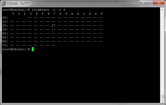
I2C devices 加到Intel Edison 其實很簡單,做法與arduino相同, 接上I2C device到 Edison Arduino後(藉由 S4A IO Board容易連接,請接到A4A5 位置),可以試著檢查系統是不是有偵測到裝置,command如 " i2cdetect -y -r 6 " , 直此命令後可以看到裝置的 I2C address. 注意的是Intel Edison 的 I2C bus是在 bus 6(Different to Raspberry Pi).
此實驗LCD顯示 Edison IP address, 然後User透過WIFI在瀏覽器上控制LED ON/OFF.
使用材料(
Materials):
1. Intel Edison + Arduino Breakout Kit
2. S4A IO Board
3. I2C LCD1602
4. LED Terminal
首先, 把所有東西都接上去, 如下圖 , LCD1602接到 IO Board的 A4A5 位置, LED Terminal接到 D2D3 孔位.
1. 進入 Edison board system, 然後輸入 如下圖.
LCD1602的 I2C address is 0x27
2. Open Arduino IDE, copy the below sketch and paste it to Arduino IDE.
#include <SPI.h>
#include <WiFi.h>
#include <Wire.h>
#include <LiquidCrystal_I2C.h>
char ssid[] = "xxxxxxx"; // your network SSID (name)
char pass[] = "xxxxxxx"; // your network password
int keyIndex = 0; // your network key Index number (needed only for WEP)
LiquidCrystal_I2C lcd(0x27,16,2); // set the LCD address to 0x27 for a 16 chars and 2 line display
int status = WL_IDLE_STATUS;
WiFiServer server(8080);
void setup() {
Serial.begin(9600); // initialize serial communication
pinMode(2, OUTPUT); // set the LED pin mode
lcd.init(); // initialize the lcd
// Print a message to the LCD.
lcd.backlight();
lcd.print("Connecting...");
// check for the presence of the shield:
if (WiFi.status() == WL_NO_SHIELD) {
Serial.println("WiFi shield not present");
while(true); // don't continue
}
String fv = WiFi.firmwareVersion();
if( fv != "1.1.0" )
Serial.println("Please upgrade the firmware");
// attempt to connect to Wifi network:
while ( status != WL_CONNECTED) {
Serial.print("Attempting to connect to Network named: ");
Serial.println(ssid); // print the network name (SSID);
// Connect to WPA/WPA2 network. Change this line if using open or WEP network:
status = WiFi.begin(ssid, pass);
// wait 10 seconds for connection:
delay(10000);
}
server.begin(); // start the web server on port 80
printWifiStatus(); // you're connected now, so print out the status
}
void loop() {
WiFiClient client = server.available(); // listen for incoming clients
if (client) { // if you get a client,
Serial.println("new client"); // print a message out the serial port
String currentLine = ""; // make a String to hold incoming data from the client
while (client.connected()) { // loop while the client's connected
if (client.available()) { // if there's bytes to read from the client,
char c = client.read(); // read a byte, then
Serial.write(c); // print it out the serial monitor
if (c == '\n') { // if the byte is a newline character
// if the current line is blank, you got two newline characters in a row.
// that's the end of the client HTTP request, so send a response:
if (currentLine.length() == 0) {
// HTTP headers always start with a response code (e.g. HTTP/1.1 200 OK)
// and a content-type so the client knows what's coming, then a blank line:
client.println("HTTP/1.1 200 OK");
client.println("Content-type:text/html");
client.println();
// the content of the HTTP response follows the header:
client.print("Click <a href=\"/H\">here</a> turn the LED on pin 9 on<br>");
client.print("Click <a href=\"/L\">here</a> turn the LED on pin 9 off<br>");
// The HTTP response ends with another blank line:
client.println();
// break out of the while loop:
break;
}
else { // if you got a newline, then clear currentLine:
currentLine = "";
}
}
else if (c != '\r') { // if you got anything else but a carriage return character,
currentLine += c; // add it to the end of the currentLine
}
// Check to see if the client request was "GET /H" or "GET /L":
if (currentLine.endsWith("GET /H")) {
digitalWrite(2, HIGH); // GET /H turns the LED on
Serial.println("LED ON");
}
if (currentLine.endsWith("GET /L")) {
digitalWrite(2, LOW); // GET /L turns the LED off
Serial.println("LED OFF");
}
}
}
// close the connection:
client.stop();
Serial.println("client disonnected");
}
}
void printWifiStatus() {
// print the SSID of the network you're attached to:
Serial.print("SSID: ");
Serial.println(WiFi.SSID());
// print your WiFi shield's IP address:
IPAddress ip = WiFi.localIP();
Serial.print("IP Address: ");
Serial.println(ip);
// print the received signal strength:
long rssi = WiFi.RSSI();
Serial.print("signal strength (RSSI):");
Serial.print(rssi);
Serial.println(" dBm");
// print where to go in a browser:
Serial.print("To see this page in action, open a browser to http://");
Serial.println(ip);
lcd.clear();
lcd.print(ip);
}
然後自行修改 ssid 和 pass 參數符合自己的 Router. (請自行下載 LiquidCrystal_I2C library)
3. Upload sketch to Edison. 等幾十秒鐘LCD會顯示 IP address.
4. 開啟PC瀏覽器輸入IP address and port 8080, 例如 http://192.168.1.28:8080
請參考影片!
https://youtu.be/vfpTnySBfiw